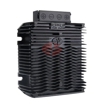
12V to 24V Step Up Converter 30A/50A
Heavy-current continuous boost designed for dual-battery vehicles, commercial trucks, and high-flow bilge pumps.
- Input Range9–18V DC
- Output Voltage24.0V DC ±1%
- Max Current50A (1200W)
- ProtectionIP68 Waterproof
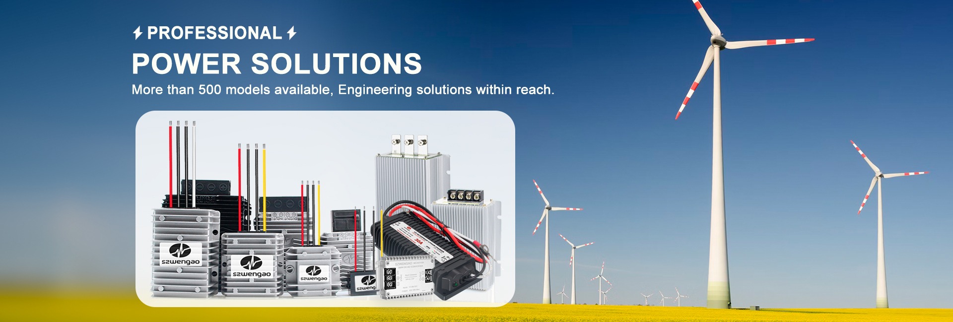
Direct factory OEM/ODM engineering from Shenzhen Eltrum Electronic Co., Ltd. Ultra-reliable step-up conversion from 12V/24V to 24V, 36V, and 48V up to 50A with IP68 waterproof encapsulation.
Addressing the core physics, parasitic losses, and design pitfalls global system integrators and power engineers encounter when deploying high-current step-up conversion.
In electrical powertrain systems, mobile industrial automation, commercial marine setups, and decentralized off-grid renewable installations, system voltages rarely remain uniform. A DC-DC step up boost converter serves as the critical active power conversion link, transforming an unstabilized, low-voltage DC bus—most commonly from lead-acid, lithium iron phosphate (LiFePO4), or alternating solar arrays—into a well-regulated higher potential. Whether lifting an automotive 12V bus to a 24V hydraulic valve rail, powering a 48V high-torque brushless DC (BLDC) motor from a 24V onboard battery, or boosting low-potential solar inputs, modern step-up converters must balance high continuous current throughput with thermal efficiency, electromagnetic compliance (EMC), and minimal ripple.
Unlike basic buck topology where input current is pulsed and output current is smooth, a classic non-isolated boost converter draws continuous current from the input inductor while delivering discontinuous, pulsating current to the output through a freewheeling diode or synchronous MOSFET switch. The governing continuous conduction mode (CCM) ideal relationship is defined by:
Where D represents the duty cycle and η represents real conversion efficiency. Hardware designers must recognize that as input voltage sags (for instance, when a 12V LiFePO4 battery drops to its cut-off limit of 10.5V under load), the required duty cycle increases sharply. Because input current scales inversely with input voltage, operating near maximum step-up ratios dramatically intensifies copper (I²R) losses in the inductor windings, drain-source on-resistance (Rds_on) losses in the switching MOSFETs, and equivalent series resistance (ESR) heating across the output smoothing capacitors. At Shenzhen Eltrum Electronic Co., Ltd., our engineering process counters these constraints by incorporating planar magnetic structures, ultra-low Rds_on power FETs, and multi-phase interleaved switching stages to maintain conversion efficiency above 95% even under peak load transitions.
One of the most frequent technical inquiries answered by our application engineers concerns why a conventional boost converter cannot naturally decouple input from output during short-circuit conditions. In an asynchronous boost architecture, an unobstructed DC path exists through the main inductor and freewheeling diode straight to the load capacitor.
When cold-starting into heavy capacitive loads or downstream inverters, unrestricted inrush currents can easily weld relay contacts or cause upstream battery management systems (BMS) to trigger over-current protection. Shenzhen Eltrum Electronic Co., Ltd. addresses this across our high-power boost converter families by integrating active N-channel bypass switches, smart soft-start slew rate controllers, and optional galvanic isolation configurations.
Proven industrial models delivering sustained current output under harsh operating temperatures (-40°C to +85°C). Fully potted in heavy-duty aluminum heatsink enclosures.
Heavy-current continuous boost designed for dual-battery vehicles, commercial trucks, and high-flow bilge pumps.
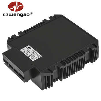
Enables 12V vehicular systems to power 48V telecommunication nodes, Starlink systems, and POE switches.
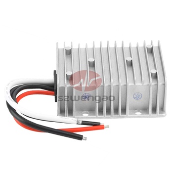
Optimized for AGVs, warehouse robotics, and marine systems needing reliable 48V power from 24V banks.
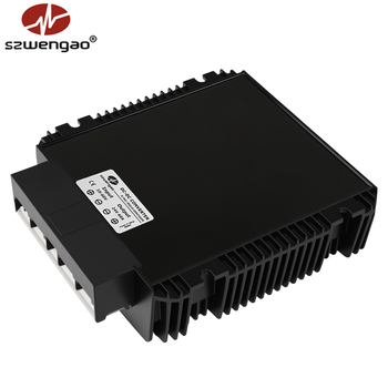
Microprocessor-managed voltage stabilization with remote RS485 telemetry for intelligent battery banks.
Where power architecture is moving in 2025–2030: GaN switches, smart edge telemetry, and circular supply chain transparency.
F_sw > 500 kHz / η > 97%
The transition from silicon MOSFETs to Gallium Nitride (GaN) and Silicon Carbide (SiC) semiconductors allows dramatically faster switching frequencies with ultra-low gate charges. This reduces the physical size of magnetic inductors and smoothing capacitors by over 40%, elevating power density while slashing thermal dissipation inside sealed IP67/IP68 enclosures.
Automotive & Edge Computing
Commercial fleets, heavy utility robotics, and marine electrical systems are rapidly migrating from traditional 12V architectures toward 48V standards. Stepping up 12V starter or secondary packs to 48V allows wiring harnesses to carry a quarter of the amperage for the same wattage, eliminating parasitic line drops and significantly trimming vehicle curb weight.
CANbus & RS485 Modbus
Modern buyers are shifting away from static "black box" converters. Enterprise procurement increasingly specifies digitally controlled boost converters capable of real-time voltage/current logging, internal PCB junction temperature monitoring, and fault reporting over CANbus or RS485, integrating seamlessly into vehicle management dashboards.
Direct Manufacturer OEM Audit
With heightened international compliance standards and trade logistics hurdles, B2B procurement managers are actively consolidating vendors. Engineering teams prefer working directly with vertically integrated manufacturers who conduct in-house SMT assembly, automated AOI/ICT testing, potting, and comprehensive load burn-in under ISO 9001 governance.
Compare standard engineering configurations engineered by Shenzhen Eltrum Electronic Co., Ltd. Modified electrical characteristics and custom packaging available upon request.
| Model Family | Input Voltage | Output Voltage | Rated Current | Efficiency | Enclosure / Protection | RFQ Action |
|---|---|---|---|---|---|---|
| WG-12S2420 | 9–18V DC | 24V DC | 20A (480W) | 95.2% | Die-cast Aluminum / IP68 | Get a Quote → |
| WG-12S2450 | 10–18V DC | 24V DC | 50A (1200W) | 94.8% | Extruded Aluminum Fin / IP68 | Get a Quote → |
| WG-12S4810 | 10–20V DC | 48V DC | 10A (480W) | 95.0% | Die-cast Aluminum / IP68 | Get a Quote → |
| WG-12S4820 | 11–24V DC | 48V DC | 20A (960W) | 95.6% | Heavy-duty Heatsink / IP68 | Get a Quote → |
| WG-24S4815 | 18–36V DC | 48V DC | 15A (720W) | 96.1% | Waterproof Encapsulated / IP68 | Get a Quote → |
| WG-24S4830 | 20–36V DC | 48V DC | 30A (1440W) | 95.8% | Active Heat Pipe Shell / IP67 | Get a Quote → |
| Custom OEM Module | Custom (8–60V) | Custom (15–90V) | Up to 100A | ≥95.0% | Form-factor, harness & RS485 customizable | Get a Quote → |
2015Established 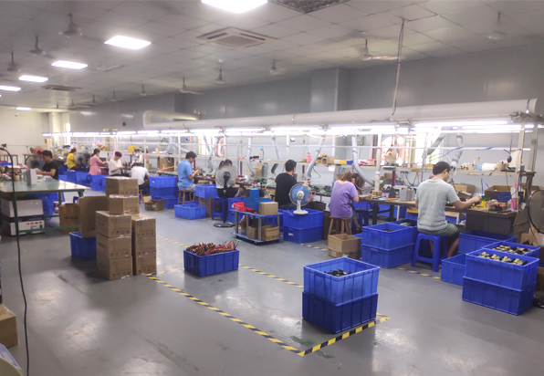
Shenzhen Eltrum Electronic Co., Ltd. is a high-technology enterprise specializing in the design, development, and mass manufacturing of industrial-grade DC-DC converters (boost, buck, buck-boost, and isolated topologies), high-frequency switching power supplies, and waterproof LiFePO4 battery charging modules. Founded in 2015 and based in Shenzhen, China, our manufacturing infrastructure operates in strict adherence to ISO 9001 quality management guidelines.
Our power modules are deployed globally across North America, Europe, Australia, Japan, and Southeast Asia in critical applications such as marine navigation, municipal bus retrofits, commercial robotics, telecom power shelves, and high-altitude solar base stations. Every product meets stringent international CE and RoHS standards. Furthermore, our legal production capabilities have been verified on-site by international inspection bodies.
Power conversion failure in the field costs exponentially more than the unit itself. That is why Shenzhen Eltrum Electronic Co., Ltd. enforces an uncompromising 5-stage QC methodology across every production batch:
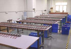
Comprehensive burn-in and active load monitoring ensures field longevity and minimal RMA rates.
Direct technical answers to the most common queries engineers and global supply chain buyers ask regarding DC-DC step up boost converters.
Because energy conservation requires Pin ≥ Pout, your input current is significantly larger than your output current. Use the formula: I_in = (V_out × I_out) / (V_in_min × η).
For example, delivering 24V @ 20A (480W) with 94% efficiency when your 12V battery discharges to 10.5V requires: (24 × 20) / (10.5 × 0.94) = 48.6A continuous input current. Sizing cables or fuses based on nominal 12V or load amperage will lead to catastrophic nuisance tripping and excessive I²R voltage drop along input conductors.
A non-isolated boost topology features a fundamental physical direct circuit loop from input to output across the series inductor and freewheeling diode. If a direct short-circuit occurs at the output terminals, current flows uncontrolled from the source battery directly through the inductor and diode to ground, bypassing MOSFET switching control. To achieve full dead-short survivability, Shenzhen Eltrum Electronic Co., Ltd. incorporates electronic circuit breaker MOSFET disconnects or offers true isolated DC-DC converters.
A standard boost converter operates as a Constant Voltage (CV) power supply. It will deliver maximum current until it hits an over-current trip point if connected directly to a depleted battery. To safely charge lithium (LiFePO4) or AGM batteries, you must utilize a unit equipped with a dedicated Constant Current / Constant Voltage (CC/CV) charging profile and temperature compensation, such as our WG-series DC-DC battery chargers.
While our aluminum enclosures with epoxy/silicone encapsulation conduct heat efficiently away from semiconductors to the outer shell, they rely on ambient air convection or contact conduction. If installed in an unventilated battery box or hot vehicle engine bay exceeding +50°C ambient, we recommend derating continuous output current by 20%–30% or mounting the unit flat against an auxiliary metal chassis using thermal conductive paste.
Shenzhen Eltrum Electronic Co., Ltd. offers an engineer-friendly MOQ of just 5 units for standard catalog boost converters to facilitate prototype validation. For bespoke OEM/ODM projects (custom step-up ratios, custom wiring pigtails, waterproof mating connectors, or RS485 digital control), prototype validation samples are typically delivered within 7 to 15 business days.
Fast switching transients inherent to boost converters can produce high-frequency conducted and radiated emissions. Our hardware incorporates multi-stage LC input and output filter networks, shielded toroid or planar inductors, and full solid aluminum shielding to ensure our modules comfortably pass CE (EN 55032 Class B) and RoHS industrial emissions and immunity criteria.
Connect directly with our senior power electronics engineers. Request detailed datasheets, 3D CAD step files, or receive a fast quotation tailored to your exact voltage and current specifications.