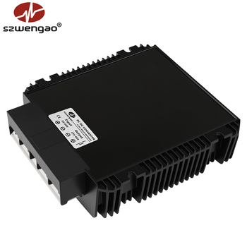
1500W High-Power Buck-Boost (RS485)
- Input Range10–60V DC
- Output Voltage12 / 24 / 28 / 48V DC
- Rated Power1500W (High Current)
- CommunicationRS485 MODBUS RTU
When input busbars swing dynamically above and below your nominal system voltage—plunging during cold-cranking cycles and spiking during solar harvest—only a synchronous non-isolated buck boost DC-DC converter guarantees seamless voltage stabilization without ripple collapse or brown-out dropouts. Produced by Shenzhen Eltrum Electronic Co., Ltd. under strict ISO 9001 precision manufacturing standards.
Modern power systems deployed across autonomous guided vehicles (AGVs), recreational vehicles, high-current marine electronics, and off-grid telecommunication stations operate along extremely unpredictable DC rails. A standard buck converter fails entirely when battery terminal voltage sags below the regulated threshold under heavy starter-motor loads; conversely, a traditional boost topology cannot regulate when incoming solar arrays or alternator dump transients spike beyond target voltage.
A high-performance Buck Boost DC-DC Converter eliminates this operational bottleneck. Unlike primitive single-switch inverting SEPIC or flyback topologies that introduce extreme switching stress, sluggish transient response, and inverted output polarities, Shenzhen Eltrum Electronic Co., Ltd. adopts a high-efficiency 4-switch synchronous H-bridge architecture. By modulating internal low-RDS(on) MOSFET arrays with digital closed-loop PWM/PFM firmware, our converters transition seamlessly between buck mode, boost mode, and 4-switch buck-boost overlap states. This ensures absolute ±1% line regulation across unpredictable 8V to 40V, 9V to 40V, and 10V to 60V power grids without phase margin degradation or inductor saturation.
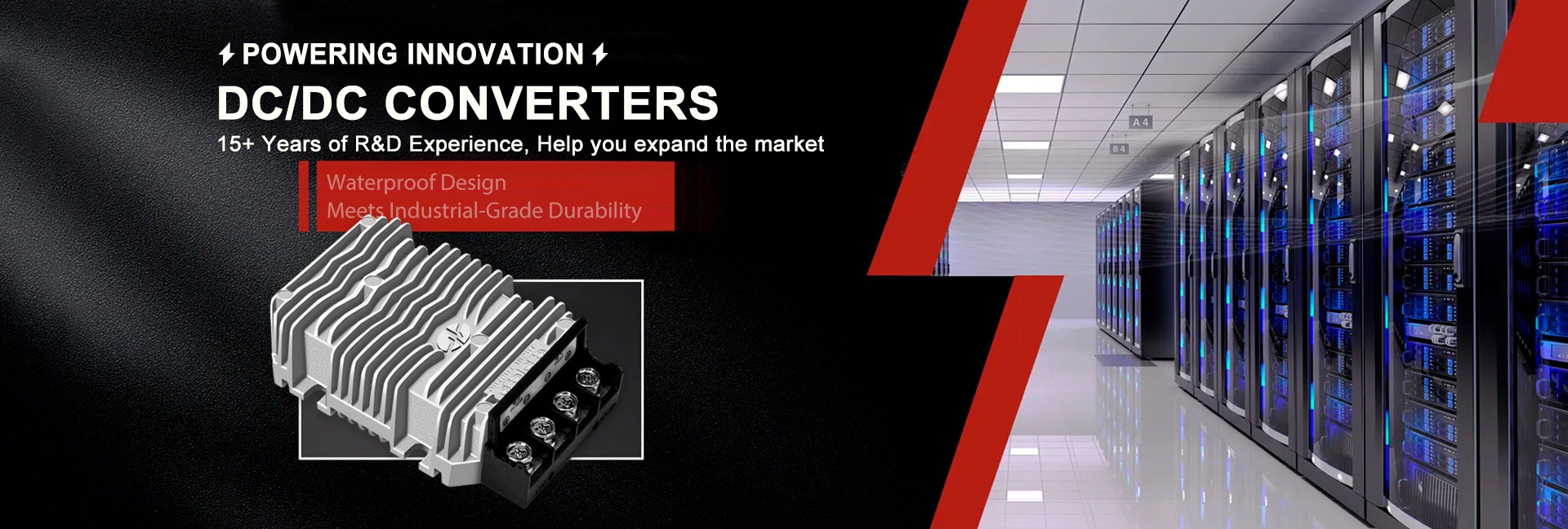
Engineered for high current density, extreme thermal stability (-40°C to +85°C), and uncompromising electromagnetic compliance across commercial fleets and industrial automation.
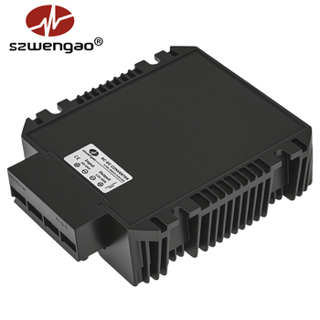
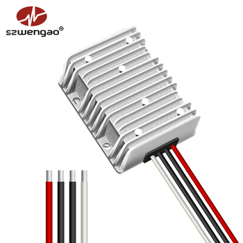
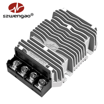
Choosing the correct circuit architecture prevents unnecessary thermal stress, component failure, and costly field recalls. Evaluate your engineering requirements below.
| Conversion Topology | Input / Output Voltage Rule | Peak Efficiency | Grounding Architecture | Typical Ingress & Mounting | Best Suited Application Context |
|---|---|---|---|---|---|
| Synchronous Buck-Boost | Vin crosses Vout (e.g. 9–40V → 12V/24V) | 94% – 97% | Non-Isolated Common Ground | IP68 Potted Aluminum Heatsink | Fluctuating battery banks, marine electronics, RV auxiliaries, solar microgrids. |
| Synchronous Buck | Vin,min > Vout + Headroom Drop | 95% – 98% | Non-Isolated Common Ground | IP68 Potted / Open-Frame | Step-down conversions: 24V/48V truck packs to 12V telemetry, USB distribution. |
| Synchronous Boost | Vin,max < Vout (Always Step-Up) | 93% – 96% | Non-Isolated Common Ground | IP68 Sealed Extruded Housing | Step-up conversions: 12V systems driving 24V or 48V actuators, lidar, LED arrays. |
| Isolated Flyback / Forward | Any Input to Any Output (Galvanic Barrier) | 86% – 92% | Complete Galvanic Isolation (>1500V DC) | Sealed Brick / Flanged Case | Telecom racks, ground-loop noise decoupling, forklift traction pack electronics. |
Procurement directors and system architects are modernizing their supply chains to meet shifting power density, regulatory, and digital control demands.
Global procurement is pivoting towards Silicon Carbide (SiC) and Gallium Nitride (GaN) switching bridges. These wide-bandgap materials allow switching frequencies exceeding 500 kHz, shrinking magnetic chokes by 45% while preserving efficiency above 97% even under 100°C baseplate temperatures.
Driven by robotics, telecom, and commercial EV electrification, the migration to 48V DC architectures has accelerated demand for bidirectional and high-power buck-boost modules capable of operating from 10V to 60V seamlessly without line sag during regenerative braking.
Hardware buyers no longer accept "black box" power supplies. Emerging tenders demand intelligent buck-boost converters equipped with isolated RS485 MODBUS RTU or CAN bus communication for predictive thermal monitoring, dynamic voltage trim, and telemetry reporting.
As deployments expand across harsh maritime, agricultural, and off-grid mining systems, international purchasers mandate IP67/IP68 potting compound encapsulation that resists thermal shock, dielectric breakdown, and corrosive moisture intrusion.
The development of buck-boost power conversion has transitioned through three distinct technological eras over the past twenty years:
Generation 1 (Classical Inverting & SEPIC Topologies): Early topologies suffered from high voltage stress on passive switches, high ESR losses across series coupling capacitors, and inverted output polarities that required complex isolation schemes. Thermal dissipation was excessive, limiting output to low current densities.
Generation 2 (Synchronous Four-Switch Analog Modulation): Integrating active synchronous MOSFETs on both input and output legs eliminated diode forward-voltage drops (0.7V diode losses replaced by milliohm RDS(on) channels). Analog PWM controllers handled buck-or-boost transitions, achieving 92% to 95% efficiency.
Generation 3 (Digital Multiphase Architecture by Eltrum): Modern designs from Shenzhen Eltrum Electronic Co., Ltd. combine digital core microcontrollers, custom planar magnetics, and advanced synchronous gate drivers. Our architecture features zero-current switching (ZCS) and zero-voltage switching (ZVS) resonant aids, dynamic soft-start sequencing, and automated dead-time control, pushing theoretical boundaries toward 98% conversion efficiency.
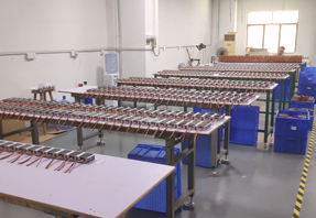
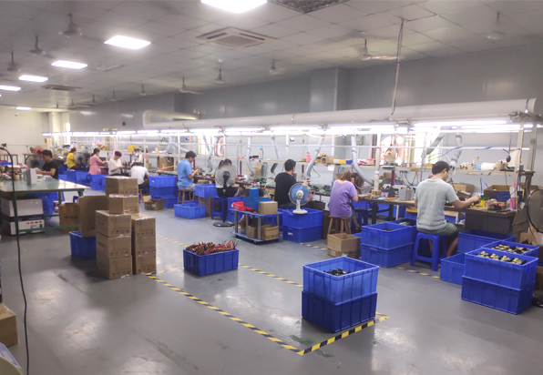
Precision SMT and automated robotic assembly lines at Shenzhen Eltrum Electronic Co., Ltd.
Founded in 2015, we operate advanced assembly, vacuum potting, and high-voltage burn-in testing facilities certified under ISO 9001 quality management.
Shenzhen Eltrum Electronic Co., Ltd. specializes in the research, development, and high-volume manufacture of DC-DC converters, buck-boost voltage regulators, battery charging modules, and isolated power supplies. Our engineering catalog spans more than 500 validated production models trusted by tier-1 system integrators across North America, Europe, Australia, and Asia-Pacific.
Our facility has undergone stringent onsite verification by international third-party certification authorities. Every power module is built with premium components—including genuine automotive-grade low-ESR capacitors, high-permeability sendust powder cores, and thermal interface materials with superior heat conduction.
We uphold the operating principle of "Customer First, Best Service, Zero Compromise on Quality". Whether you need rapid prototype sampling starting at just 5 units or complete ODM engineering support including custom PCB layouts, private label branding, and custom connectors, our Shenzhen-based R&D team delivers dependable power hardware on time.
Comprehensive technical answers addressing voltage dips, thermal dissipation, wiring protection, and OEM customization.
Discuss your engineering requirements directly with our technical support team. Custom voltage rails, potting grades, and RS485 communication protocols tailored to your system architecture.