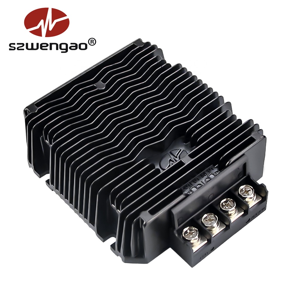
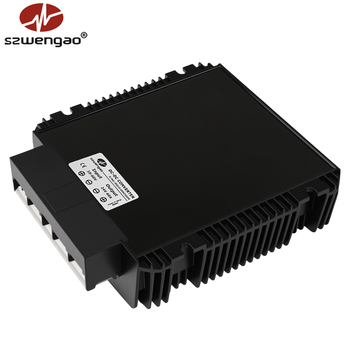
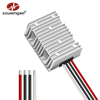
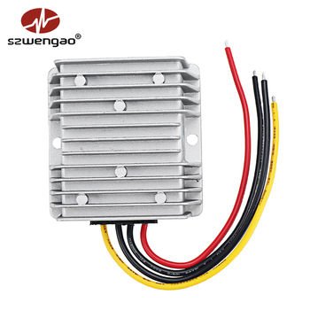
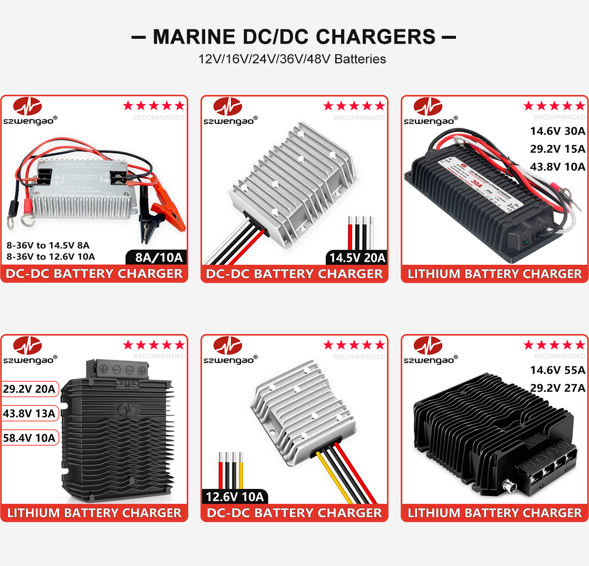
Smart 36V Lithium Battery Charger DC 12V to 43.8V 13A
- Input Voltage10.5V – 16.0V DC
- Output Profile43.8V DC @ 13A CC/CV
- Peak Efficiency≥ 94.5%
- ProtectionIP67 Waterproof / OVP
Manufactured in Shenzhen with synchronous rectification topologies, aviation-grade die-cast aluminum heat-dissipation enclosures, and full silicon potting compliant with IP67/IP68 submersible operating conditions.
A critical evaluation of switching topologies, magnetic saturation behavior, and synchronous rectification dynamics for system architects and procurement engineers.
In heavy commercial transport, off-grid renewable energy generation, autonomous robotics, and telecom field installations, stepping up an unstable or depleted low-voltage direct current (DC) rail to a rigid high-voltage distribution bus is a foundational power design problem. A standard asynchronous boost converter relies on an inductor, an active semiconductor power switch (typically an N-channel MOSFET), a freewheeling Schottky diode, and an output capacitance bank. During the switch-on state, energy accumulates inside the toroidal core of the power inductor. When the switch transitions to the off-state, the inductor's back-EMF reverses polarity, forcing current through the diode to dump stored magnetic energy into the output smoothing capacitors and load.
However, modern industrial system architects increasingly reject asynchronous topologies for mission-critical deployments due to the forward voltage drop (Vf ≈ 0.45V to 0.75V) across freewheeling diodes. In high-current installations—such as stepping up 12V to 24V at 50A—an asynchronous diode incurs conduction losses exceeding 25 to 35 Watts, transforming the converter into a massive thermal emitter. Shenzhen Eltrum Electronic Co., Ltd. resolves this bottleneck through Synchronous Rectification (SR), replacing passive rectifying diodes with ultra-low RDS(ON) trench MOSFETs controlled via precision cycle-by-cycle adaptive gate drivers. This reduces conduction resistance to under 2.5mΩ, catapulting operational conversion efficiencies beyond 95% while dramatically curbing internal junction temperatures.
The design of high-density boost converters also dictates specialized magnetics engineering. As switching frequencies rise between 100 kHz and 350 kHz, core losses caused by magnetic hysteresis and eddy currents in conventional iron powder cores grow exponentially. Premium Chinese manufacturing centers utilize Sendust (Kool Mμ), High Flux, or amorphous Nanocrystalline alloy cores. These materials exhibit near-zero magnetostriction, exceptional saturation induction (Bsat up to 1.6 Tesla), and high Curie temperatures, guaranteeing that the converter will not suffer catastrophic thermal magnetic collapse when subjected to transient startup inrush surges or extreme cold-cranking automotive conditions.
| Conversion Architecture | Typical Efficiency | Thermal Dissipation | Component Count | Dynamic Response | Recommended Sourcing Scenario |
|---|---|---|---|---|---|
| Asynchronous Boost | 84% – 89% | High (Diode Vf Drop) | Low (Cost-Optimized) | Moderate (300μs recovery) | Low current (< 5A), price-sensitive consumer loads |
| Synchronous Step-Up (SR) | 94% – 96.5% | Extremely Low (Die-Cast Sink) | Medium-High (Active Control) | Fast (75μs transient step) | Fleet vehicle telematics, Marine DC buses, Golf carts |
| Interleaved Multi-Phase Boost | 96% – 97.8% | Distributed Evenly | High (Multi-Inductor) | Superior (Ultra-low ripple) | Hydrogen fuel cell stacks, high-power DC charging |
| Isolated Flyback / Forward Boost | 88% – 92% | Moderate (Transformer Losses) | High (Galvanic Barrier) | Controlled via Optocoupler | Telecom (-48V), High-voltage rail traction systems |
How Tier-1 engineering procurement departments are restructuring direct factory sourcing contracts to address electrification megatrends, component obsolescence, and ESG supply chain scrutiny.
Procurement teams are aggressively shifting from pure silicon MOSFETs to Silicon Carbide (SiC) and Gallium Nitride (GaN) switching stages. With electron mobility up to 1000 times faster than silicon and negligible reverse recovery charge (Qrr), SiC-driven boost converters operate cleanly at higher voltages and temperatures, slashing chassis volumetric footprints by over 40% while surviving continuous 105°C automotive engine bays without thermal shutdown.
The era of passive "black-box" analog boost modules is rapidly ending. Supply chain directives from electric vehicle (EV) builders, AGV roboticists, and solar battery energy storage system (BESS) integrators mandate bidirectional communication. Converters must now report dynamic output current, real-time input bus drop, internal thermistor temperature, and fault diagnostics directly over isolated RS-485 Modbus RTU or CAN 2.0B interfaces.
Failure analysis reports from industrial deployment fields indicate that over 68% of converter breakdowns stem from environmental contamination: salt fog pitting in marine applications, diesel vibration fractures in long-haul trucks, and condensate penetration in outdoor PV arrays. High-spec procurement standards now universally enforce automated vacuum potting with thermally conductive polyurethane or silicone compounds, achieving strict IP67 or IP68 water/dust barrier ratings.
A look inside advanced Shenzhen R&D laboratories: magnetic planarization, active EMI suppression, and unified battery-to-battery charging firmware algorithms.
The traditional construction of hand-wound wire inductors around toroidal ferrite cores is experiencing a fundamental structural shift toward Planar Magnetics and Integrated Multilayer PCBs. Planar transformers and inductors replace copper wire with flat, etched copper leadframes embedded directly inside FR-4 multilayer substrate panels. This yields phenomenal thermal transfer to outer heatsinks, absolute geometric repeatability, and eliminates manufacturing variations in leakage inductance. As a direct consequence, parasitic ringing across switching nodes is virtually extinguished, enabling compliance with strict CISPR 25 Class 5 electromagnetic interference (EMI) limits without demanding oversized, heavy differential-mode input filters.
Concurrently, the dividing line between standard DC-DC step-up converters and intelligent battery chargers has permanently dissolved. As lithium iron phosphate (LiFePO4) and ternary lithium-ion chemistries dominate modern energy architecture, modern boost modules must double as precision Constant Current / Constant Voltage (CC/CV) battery management stations. When stepping up 12V alternator feeds to 29.2V or 43.8V auxiliary battery banks, the converter cannot merely deliver a static voltage rail; it must sense cell state-of-charge, throttle back charge current during low-temperature scenarios, apply float charge stabilization, and cease output immediately upon receiving high-voltage BMS disconnect triggers.
Established in 2015 in Shenzhen, China, Shenzhen Eltrum Electronic Co., Ltd. combines an ISO 9001 certified footprint, 500+ proven catalog architectures, and unyielding multi-tier QC burn-in standards.
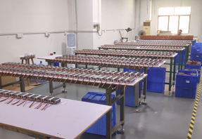
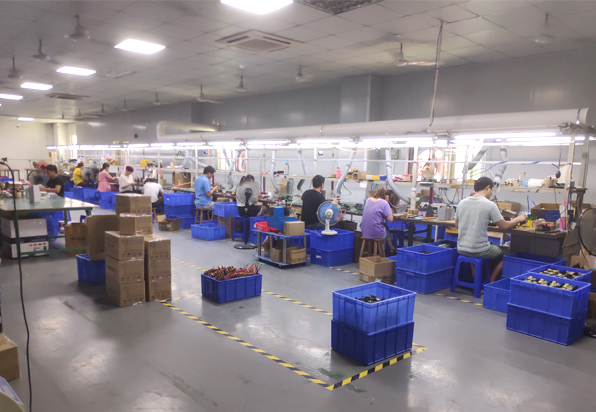
Operating from our advanced manufacturing base in the Anle Industrial Zone, Shenzhen, Shenzhen Eltrum Electronic Co., Ltd. has spent over a decade perfecting high-reliability DC-DC conversion hardware. With an on-site verified production facility spanning over 3,000 square meters and a dedicated engineering workforce of 51–100 technicians, we bridge the gap between rapid custom prototype design and multi-million-unit mass production runs.
Unlike trade brokers, every Eltrum converter undergoes 100% full-load thermal burn-in testing inside computerized environmental chambers. We maintain strict compliance with CE (EMC/LVD), RoHS, and international transportation certifications, servicing long-term OEM contracts across more than 130 destination countries throughout North America, Western Europe, Australia, and East Asia.
Detailed answers prepared by senior electrical engineers to address real-world integration, sizing, certification, and volume logistics inquiries.
Submit your input voltage envelope, desired output rail specs, and environmental constraints. Our senior application engineers in Shenzhen will assess your topology requirements and return detailed datasheets, 3D CAD models, and volume quotation structures within 24 business hours.