Featured Industrial DC-DC Boost & Step-Up Converters
Factory-verified DC-DC boost voltage converters engineered for rugged vehicular, marine, telecommunication, and energy storage platforms requiring up to 96% operational efficiency.
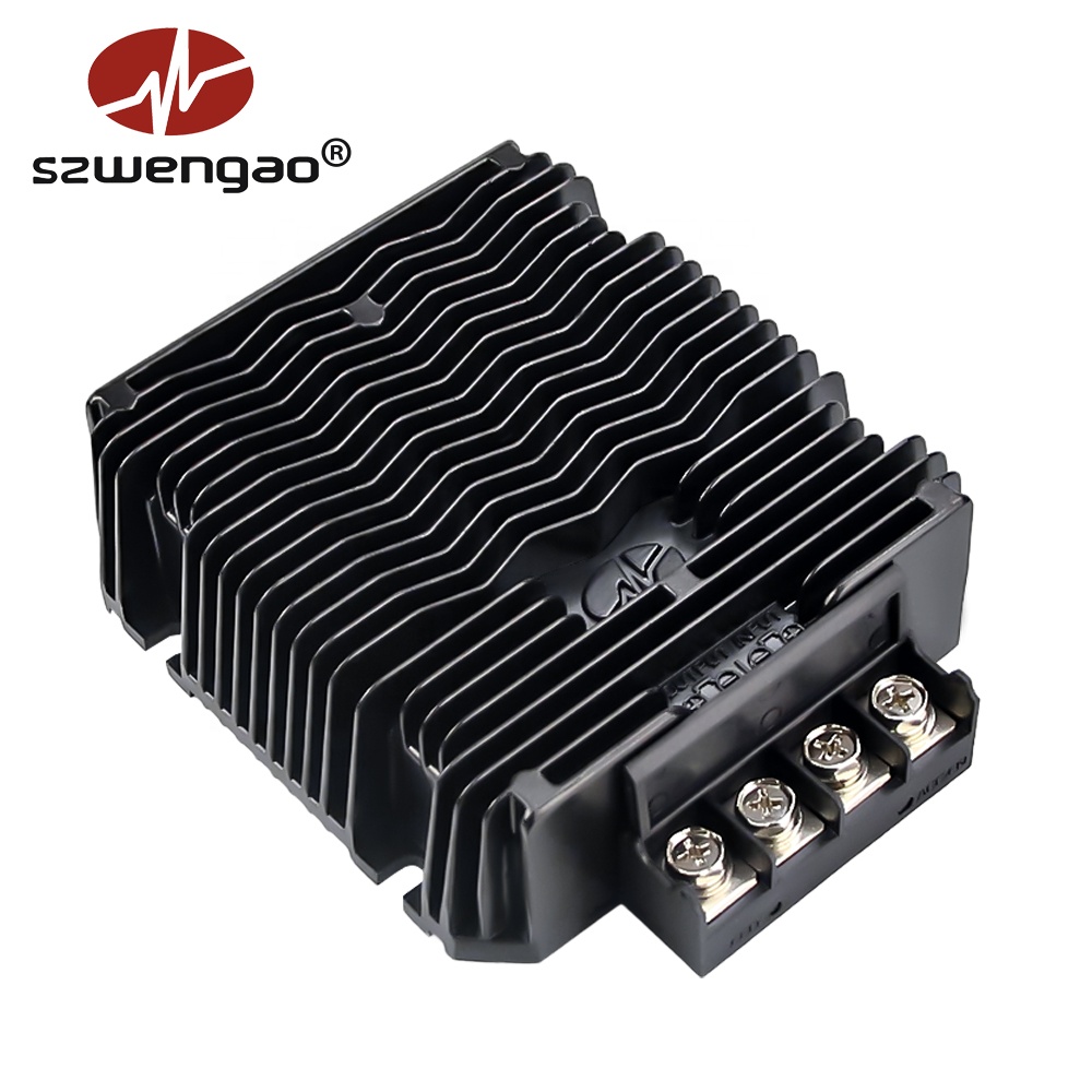
Smart 36V Lithium Battery Charger DC 12V to DC 43.8V Waterproof 13A
- TopologySynchronous Boost
- Input Range10V – 36V DC
- Output Rating43.8V @ 13A (570W)
- Ingress RatingIP68 Hermetic
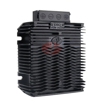
12V to 24V / 48V Heavy-Duty Step-Up Converter (Up to 50A)
- TopologyNon-Isolated Boost
- Input Voltage9V – 20V DC
- Max Output24V 50A / 48V 20A
- Peak Efficiency95.4%
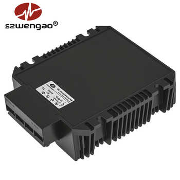
Waterproof 12V to 48V Industrial Boost Converter 12.5A–20A
- TopologySynchronous Step-Up
- Input Voltage10V – 30V DC
- Continuous PowerUp to 960W
- CasingExtruded Aluminum
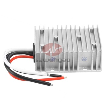
24V to 48V 10A / 15A Step-Up DC-DC Converter (720W Max)
- TopologyIndustrial Step-Up
- Input Range18V – 35V DC
- Regulation±1% Load/Line
- Target FieldsMarine & Commercial RV
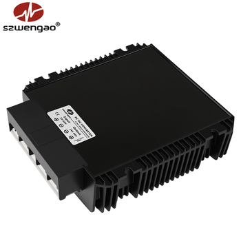
1500W High-Power Boost / Buck-Boost Unit with RS-485 Modbus
- Input Window10V – 60V Wide Input
- Output Range12V / 24V / 28V / 48V
- InterfaceRS485 Telemetry
- ConversionSynchronous Multiphase
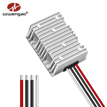
8V–40V to 13.8V 25A / 30A Continuous Step-Up/Down Stabilizer
- Input Range8V – 40V Ultra-Wide
- Nominal Vout13.8V Float Precision
- Max Current30A Peak (414W)
- ProtectionsOCP, OVP, OTP, Short
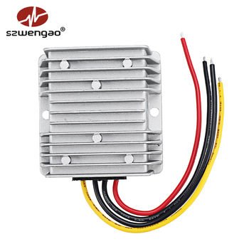
9V–40V to 24V 6A / 10A Compact Sealed Boost Regulator
- Input Range9V – 40V DC
- Output Power144W – 240W Rated
- Thermal Range-40°C to +85°C
- MTBF>120,000 Hours
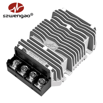
9V–40V to 28V 15A / 20A Step-Up Power Module (560W)
- Output Spec28.0V Regulated Bus
- Current Rating15A to 20A Full Load
- Thermal ShieldCast Alloy Fin Casing
- ComplianceCE / RoHS / ISO 9001
1. Anatomical Deep-Dive: DC-DC Boost Converter Topologies in High-Power OEM Systems
As an international OEM/ODM DC DC boost converter exporter, Shenzhen Eltrum Electronic Co., Ltd. architects step-up conversion circuitry around critical thermal balance, core saturation limits, and high-frequency switching dynamics. In step-up power topology, the basic voltage transfer ratio under ideal Continuous Conduction Mode (CCM) conditions is dictated by the duty cycle equation:
D = 1 - (V_in × η) / V_out
I_L(peak) = [ (V_in × D) / (2 × f_sw × L) ] + [ I_out / (1 - D) ]
Where D represents the pulse-width modulation (PWM) duty ratio, η designates the conversion efficiency, f_sw denotes switching frequency, and L defines the inductance value. For heavy commercial installations—such as boosting a 12V auxiliary system up to a 24V or 48V bus—the duty cycle typically exceeds 50% to 75%. Under such elevated conversion ratios, traditional non-synchronous boost designs incur severe parasitic forward-voltage drops across the freewheeling Schottky barrier diode (typically 0.45V to 0.75V). When handling currents of 30A to 50A, a non-synchronous diode alone dissipates between 13.5W and 37.5W of pure thermal waste, necessitating massive heatsinks and limiting thermal lifespan.
Our OEM boost converters leverage advanced Synchronous Rectification (SR). By substituting the passive freewheeling diode with ultra-low on-resistance N-channel power MOSFETs (R_DS(on) ≤ 1.8 mΩ), our topologies suppress conduction losses by over 70%, yielding overall module conversion efficiencies ranging between 94.5% and 96.8%. This thermal headroom allows our engineering team to encapsulate the complete electronic assembly inside vacuum-potted IP68 aluminum enclosures without internal cooling fans.
Multiphase Interleaved Boost
For applications exceeding 1000W, Eltrum deploys two- or three-phase interleaved boost topologies. Splitting input current across parallel inductor phases cancels input ripple current by up to 80%, reducing input capacitor stress and allowing smaller magnetics with extended lifetime.
Continuous Thermal Potting
Each converter is encapsulated in thermally conductive polyurethane or silicone potting resin (λ ≥ 1.5 W/m·K). This structural hermetic sealing prevents oxidation, insulates against vibration spikes up to 20G (MIL-STD-810H), and creates an isothermal heat transfer path.
Active EMI Mitigation (CISPR 25)
Boost topologies naturally exhibit discontinuous output current, generating high di/dt commutation noise. We incorporate symmetrical input/output CLC pi-filters combined with Spread Spectrum Frequency Modulation (SSFM) to meet strict CISPR 25 Class 5 automotive EMI limits.
2. Global Procurement Trends: Sourcing Industrial Boost Converters (2025–2030)
Procurement directors and systems engineers across Europe, North America, and the Asia-Pacific region are navigating a structural shift in distributed DC electrical architectures. Driven by electrification across utility transport, commercial marine vessels, autonomous mobile robots (AMRs), and off-grid solar microgrids, the technical criteria for selecting an OEM/ODM DC DC boost converter exporter have evolved dramatically beyond basic unit pricing.
Key procurement vectors transforming B2B purchasing decisions include:
A. Transition to 48V Zonal Power Distribution: Commercial vehicles, telecom nodes, and heavy agricultural equipment are standardizing around 48V DC buses to slash resistive wiring losses (I²R) by up to 75% compared to legacy 12V/24V cabling harnesses. Procurement teams require boost converter exporters to deliver high-density 12V-to-48V and 24V-to-48V bidirectional and unidirectional modules capable of handling dynamic load spikes from servo winches, radar transmitters, and LiFePO4 battery pack charging.
B. Total Cost of Ownership (TCO) Prioritizing MTBF: Equipment downtime in off-grid telecom stations or mining vehicles can incur catastrophic hourly overhead. Buyers now mandate verifiable Mean Time Between Failures (MTBF) exceeding 100,000 to 150,000 hours at 40°C ambient temperatures. Shenzhen Eltrum achieves these longevity milestones through 100% full-load burn-in screening, automotive-grade solid aluminum electrolytic capacitors, and conservative thermal derating protocols.
C. Intelligent Telemetry & Field Programmability: Fixed-voltage analog converters are rapidly losing ground to digitally regulated platforms featuring isolated RS-485, CAN bus 2.0B, or Modbus protocols. Modern B2B buyers expect the ability to dynamically modulate output float voltages, set current limit thresholds, log thermal histories, and query diagnostic fault codes via host vehicle master controllers.
3. Technological Evolution: Next-Generation Wide Bandgap (GaN/SiC) & Magnetics
The core frontier in modern DC-DC boost design lies in overcoming switching frequency bottlenecks. Conventional silicon (Si) MOSFETs suffer from reverse-recovery charge (Q_rr) and gate charge (Q_g) limitations that typically constrain switching frequencies to 80kHz – 150kHz in modules rated above 500W. This restriction mandates bulky toroidal powder cores and massive filtering capacitor banks.
Shenzhen Eltrum Electronic Co., Ltd. is actively deploying Wide Bandgap (WBG) power switches—specifically Gallium Nitride (GaN) HEMTs for low-to-medium voltage inputs (≤60V) and Silicon Carbide (SiC) power MOSFETs for elevated industrial inputs (up to 90V–120V):
| Performance Parameter | Legacy Silicon (Si) MOSFET | Eltrum Next-Gen GaN / SiC SR | Direct OEM Engineering Benefit |
|---|---|---|---|
| Switching Frequency (f_sw) | 80 kHz – 150 kHz | 250 kHz – 500 kHz+ | 60% Volume Reduction in Cores |
| Reverse Recovery Charge (Q_rr) | High (Parasitic Diode) | Near Zero (Zero Q_rr in GaN) | Eliminates Switching Spikes |
| Full-Load Thermal Efficiency | 90.0% – 92.5% | 95.5% – 97.2% | 3x Reduction in Dissipated Heat |
| Volumetric Power Density | 12 W / in³ | 35 W – 55 W / in³ | Ultra-Compact Enclosure Footprint |
| Transient Recovery Time | >350 μs (Load 10% to 90%) | <60 μs | Tight Regulation under Dynamic Cranking |
Complementing WBG semiconductors, Eltrum utilizes custom Planar Transformers & Flat-Wire Helical Inductors. By replacing conventional round copper wire windings with flat copper foil ribbons, skin-effect and proximity-effect AC copper losses are minimized by up to 65% at high frequencies. This advances reliability under severe continuous vibration environments such as marine trolling motors, golf cart drivetrain controllers, and long-haul commercial truck cabins.
4. Shenzhen Eltrum Electronic Co., Ltd.: Your Strategic OEM/ODM Partner
Established in 2015 and operating from our state-of-the-art facility in Shenzhen, China, Shenzhen Eltrum Electronic Co., Ltd. has grown into a globally verified designer and manufacturer of DC-DC converters, isolated power supplies, and smart LiFePO4 battery charging modules. Exporting to over 130 countries across North America, the European Union, Australia, Japan, and Southeast Asia, we maintain strict adherence to our core tenet: "Customer First, Best Service, Flawless Engineering."
End-to-End In-House SMT Lines
Our 3,000 m² Shenzhen manufacturing plant houses multi-line high-precision Surface Mount Technology (SMT) equipment, dual-wave soldering stations, and automated optical inspection (AOI) machines ensuring micron-level placement precision on all double-sided power boards.
100% Thermal Burn-In & ATE Testing
No converter leaves our loading dock without passing 100% Automated Test Equipment (ATE) verification followed by 4 to 8 hours of continuous full-load burn-in screening inside 50°C accelerated thermal chambers to eliminate infant mortality.
Turnkey OEM/ODM Engineering Service
From non-standard input voltages (e.g. 18V–90V wide inputs), custom multi-stage LiFePO4 / LTO charging algorithms, customized IP68 connectors (Deutsch, Anderson, Molex), to private buyer labeling, our R&D engineering team offers rapid prototyping from 5 units.
All converter models comply fully with CE (LVD/EMC) directives, RoHS 3 (EU 2015/863) environmental compliance, and operate within strict ISO 9001:2015 quality management procedures. Legal enterprise credentials and on-site factory capabilities are audited and authenticated by international third-party inspection firms.
5. Engineering Decision Framework: Selecting the Optimal Conversion Topology
Selecting an incorrect topology creates systemic field failures, thermal shut-downs, or battery over-discharge issues. Below is our senior engineering evaluation matrix contrasting synchronous boost with alternative conversion families:
| Topology | Input vs Output Relation | Typical Input Range | Output Voltage Options | Ideal Application Use-Case |
|---|---|---|---|---|
| DC-DC Boost (Step-Up) | V_in < V_out Always | 9V – 20V / 18V – 35V | 24V, 28V, 36V, 48V | Raising 12V/24V battery systems to drive 48V motors, LED bars, radar, or audio amplifiers. |
| DC-DC Buck (Step-Down) | V_in > V_out Always | 24V, 48V, 60V, 72V, 90V | 5V, 12V, 13.8V, 24V | Stepping down high-voltage traction batteries (golf carts, forklifts, trucks) to power 12V accessories. |
| Buck-Boost (Stabilizer) | V_in Crosses V_out Window | 8V – 40V / 10V – 60V | 12V, 13.8V, 19V, 24V | Critical equipment requiring steady 12V or 24V rails while input battery sags under cranking down to 8.5V. |
| Galvanically Isolated | Separate Earth Grounds | 18V – 36V / 36V – 75V | 5V, 12V, 24V | Telecom racks, marine electronics, noise-sensitive medical carts where ground loop isolation is mandated. |
Frequently Asked Questions by OEM Procurement Teams
Detailed answers directly from our power supply engineers regarding custom specifications, lead times, reliability validation, and international shipping terms.
What is the minimum order quantity (MOQ) for custom OEM/ODM DC-DC boost converters?
How does your boost converter protect against reverse polarity and input over-voltage spikes?
What are the thermal derating rules when mounting the boost converter in high-ambient environments?
Can your boost converters be connected in parallel to achieve higher output amperage?
What certifications accompany export shipments to the United States, EU, and Australia?
What commercial payment methods and international delivery terms (Incoterms) do you accept?
Accelerate Your Power Conversion Development Today
Need a custom boost conversion ratio, non-standard wide input range, specialized IP68 enclosure, or rapid sample prototypes for your upcoming production run? Connect directly with our Shenzhen power engineering department.
Get Catalog