Engineering Whitepaper Analysis
The Architecture of Isolated DC-DC Conversion: Why Galvanic Isolation Dictates System Integrity
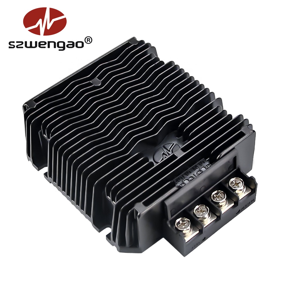
In modern industrial automation, electrified commercial mobility, and distributed telecom environments, power stability is routinely challenged by common-mode noise, ground potential shifts, and harsh inductive voltage spikes. Selecting a Custom OEM Isolated Power Module is fundamentally an architectural hedge against catastrophe. Galvanic isolation eliminates the physical conduction path between primary source power (such as noisy traction motor batteries or fluctuating solar strings) and the secondary payload logic boards. By employing magnetic flux coupling via precision-wound planar or toroidal transformers, high-voltage transients are arrested safely at the isolation barrier.
Without adequate galvanic separation, ground potential loops inevitably form. In high-current applications such as material handling AGVs or off-highway mining vehicles, several hundred amperes rushing through battery negative lines create significant resistive voltage drops. If control electronics share this non-isolated reference, digital microcontrollers and analog instrumentation encounter fluctuating ground offsets, resulting in communication dropouts, false sensor readings, and immediate silicon breakdown. Our isolated topologies utilize optical feedback or isolated digital modulators across an unbroken dielectric barrier rated from 1500V DC to 3000V DC, securing uncompromising continuous operational safety.
Engineering Selection Matrix: Isolated vs. Non-Isolated Architectures
Choosing the correct topology requires evaluating electrical safety constraints, transient severity, and structural ground paths. The comparison matrix below outlines critical design trade-offs evaluated by hardware procurement teams: